Functional: Mechanical Analysis

I looked at the performance of the first prototype according to its fundamental physical features.
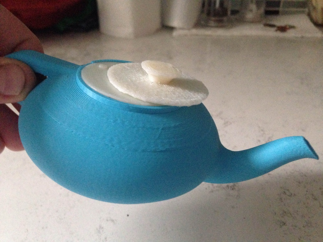
The first test looks at the capability of the spout to pour easily and without dripping. The teapot pours the water in a sufficient curve and does not drip (in the first picture, the water is leaking from the side, where the printer left a hole).
The next test consisted at looking whether the lid of the teapot would stay on the top of the teapot body once tilted for pouring. The result is that it falls down due to the inaccuracy of the grip that is supposed to be between the Cylinder and the Lid. However, it is likely that the Lid’s mass is too big for the teapot to hold it, once the centre of mass is shifted.
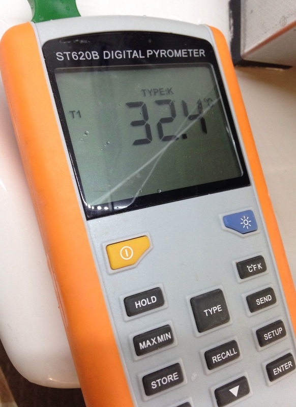
Furthermore, I was curious to see the way tea water cools down in the teapot. For this, I have taken a thermometer at the Institute of Making and used a glass teapot to model the final product which is supposed to be made of glass and contain approximately the same volume of water as the final prototype. The glass of this teapot is fairly thin and some elements (like the lid) are made of plastic.
At some places there is a gap (between the lid and the teapot body), where steam can escape, cooling the overall temperature of the brew.The procedure consisted of measuring the temperature of the brew every 30 seconds. The graph shows the time in minutes on the x-axis and temperature in Celsius on the y-axis. Ideally, the temperature would remain constant for the period of the steeping time, yet physically it is difficult to achieve such conditions. The temperature decreased on average by 5.6 °C at a room temperature of 19.7 °C. A fast decrease like this indicates the poor insulator qualities of the teapot.
At some places there is a gap (between the lid and the teapot body), where steam can escape, cooling the overall temperature of the brew.The procedure consisted of measuring the temperature of the brew every 30 seconds. The graph shows the time in minutes on the x-axis and temperature in Celsius on the y-axis. Ideally, the temperature would remain constant for the period of the steeping time, yet physically it is difficult to achieve such conditions. The temperature decreased on average by 5.6 °C at a room temperature of 19.7 °C. A fast decrease like this indicates the poor insulator qualities of the teapot.


|
|
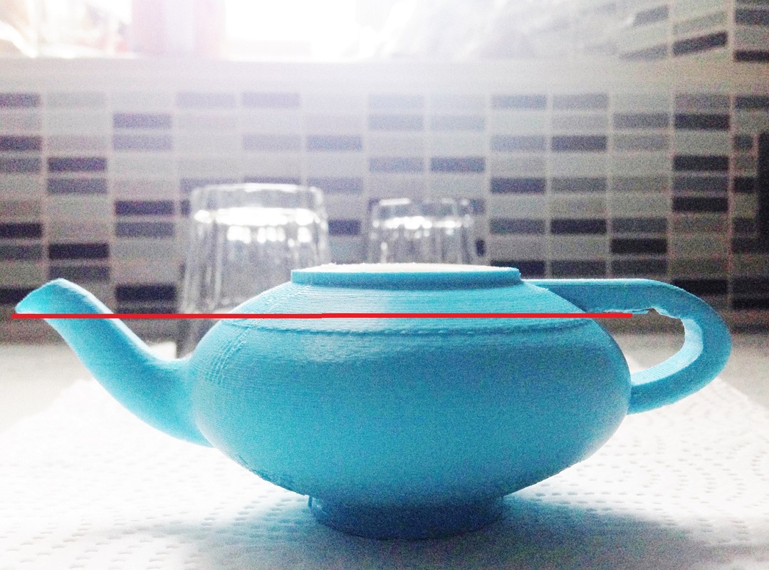
On the picture below one can see the maximum water level that the teapot can contain. It is significantly lower in comparison to the top of the teapot which means that the allocation and capacity are not at their maximum level. This should be considered in the further improvement of the design.
Functional: Quality Analysis

To try out the quality of brewing choosing a particular tea type (sencha), I have done a test to examine the taste and colour alterations by taking a sample of the brew each 30 seconds. The samples on the left are therefore 30 seconds apart each.
I have chosen green tea as it can be steeped for a short period of time (2-3 min), so the risk of the plastic melting is less. Green tea also demonstrates changes in colour easily and does not require very high temperatures (70°C, yet I performed my experiment on 60°C for safety matters).
The result showed that the best brews were the second, third and fourth. It is unlikely to obtain a very good brew in 30 seconds and the same applies to over-extracted brews too.
Mathematical Analysis
Angle Measurement
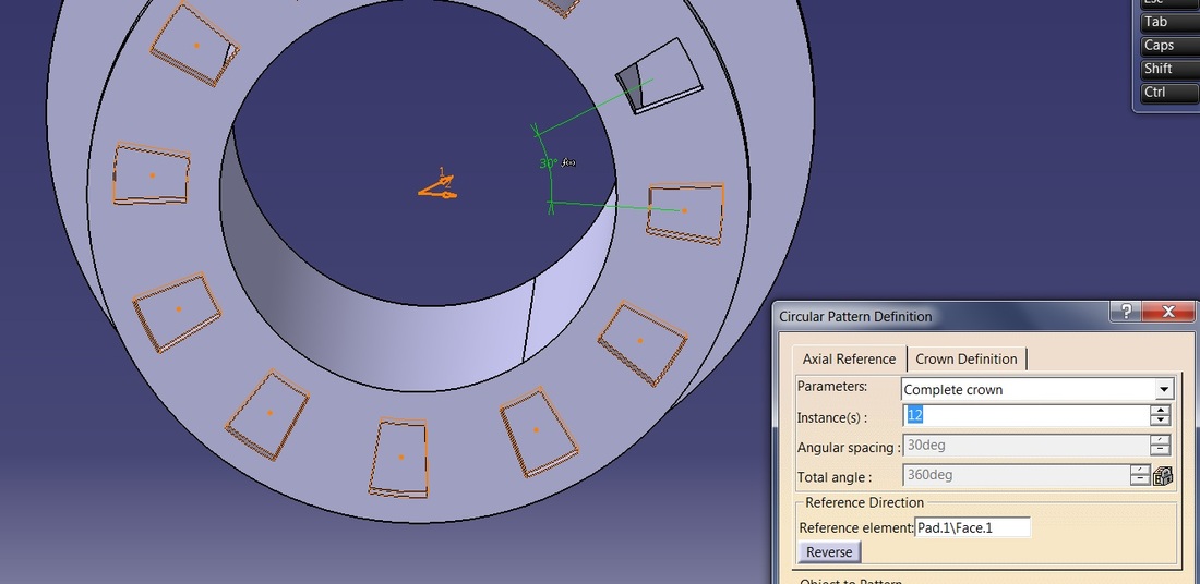
As there were multiple parts involved with connecting the lid to the filter section a few hand calculation had to be performed to ensure that when the user twisted the lid the filter would go from fully open to fully closed.
The revolution contains 12 pockets (holes). As it is 360°, to be able to position them equally, with equal space in between, I have created mirrored the holes by every 30°. Therefore the gaps had to be 15° (measured from the centre) with 15° platform between them (also measured from the centre).
As a consequence, the Lid’s revolution is similarly restricted to 30° - the protrusion restricts the magnitude to which extend the lid can turn.
Tolerance Estimation
From multiple printing and calculations it was clear that the design lacks water-tightness. The first attempts were unsuccessful in finding the right tolerance for these dimensions. Using 1 mm or 0.5 mm in radius did not function well and therefore 0.25 mm were used in most elements in contact.
"While no official engineering standard covers the process or format of tolerance analysis and stackups, these are essential components of good product design. Tolerance stackups should be used as part of the mechanical design process, both as a predictive and a problem-solving tool. The methods used to conduct a tolerance stackup depend somewhat upon the engineering dimensioning and tolerancing standards that are referenced in the engineering documentation, such as American Society of Mechanical Engineers (ASME) Y14.5, ASME Y14.41, or the relevant ISO dimensioning and tolerancing standards. Understanding the tolerances, concepts and boundaries created by these standards is vital to performing accurate calculations".
"While no official engineering standard covers the process or format of tolerance analysis and stackups, these are essential components of good product design. Tolerance stackups should be used as part of the mechanical design process, both as a predictive and a problem-solving tool. The methods used to conduct a tolerance stackup depend somewhat upon the engineering dimensioning and tolerancing standards that are referenced in the engineering documentation, such as American Society of Mechanical Engineers (ASME) Y14.5, ASME Y14.41, or the relevant ISO dimensioning and tolerancing standards. Understanding the tolerances, concepts and boundaries created by these standards is vital to performing accurate calculations".
